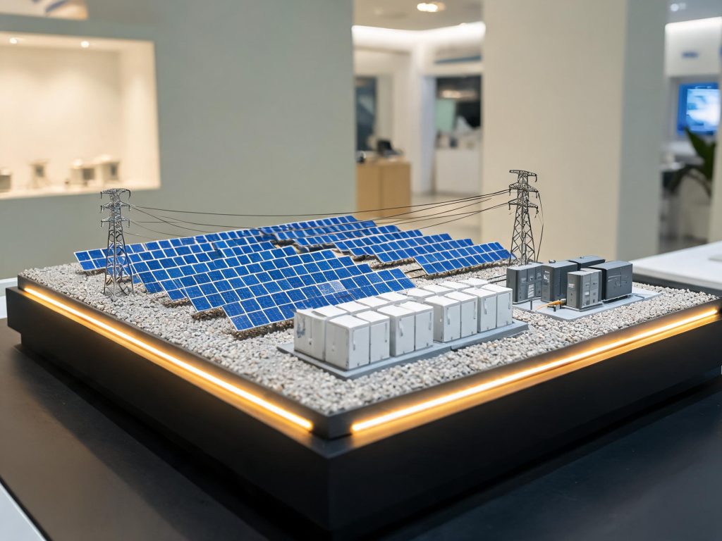
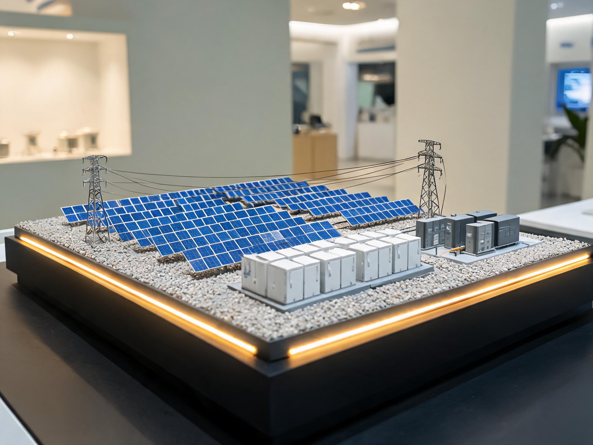
This photovoltaic and energy storage scale model turns an invisible power system into something a visitor can read in ten seconds. Built at 1:100 on a 240 cm × 140 cm base, it places solar arrays, battery containers, inverter cabinets, a substation and a transmission line on one continuous landscape — and then lights the path the electricity actually takes.
The photovoltaic and energy storage scale model is used where the audience is mixed: a corporate exhibition hall, a science museum floor, a government energy review, or a trade show where most visitors will not read a single-line diagram. The model does the explaining that a brochure cannot.
What the photovoltaic and energy storage scale model includes
The scene follows a real project rather than a generic idea of a solar farm. Array orientation, row spacing, container layout and cable routes are taken from the client’s general arrangement drawing, so engineers recognise their own site and non-technical visitors still understand the story.
Generation, storage and grid, on one base
- Solar arrays — tilted panel rows with etched cell texture, mounted on tracker or fixed frames to match the real installation
- Battery containers — storage cabinets with cooling units, door detail and hazard signage, arranged in the real cluster pattern
- Inverters and transformers — grey cabinets, busbars and a compact substation with visible connections
- Transmission — lattice pylons, insulators and catenary lines running to the edge of the base
- Site works — gravel or grass ground texture, access roads, fencing, drainage and a small control building
Current flow and working effects
LED strips run under the array rows and along the feeder cables. In demonstration mode the light travels from the panels to the inverters, into the battery containers, and out to the grid — the sequence follows the real power path, so a guide can narrate charging, discharging and export without pointing at boxes on a drawing.
Wind and hydrogen variants are built the same way: turbines rotate on geared micro-motors, electrolyser and storage tanks sit in the same visual language, and the flow lighting follows the same logic. A single exhibition stand can therefore show a hybrid energy site rather than one technology in isolation.
Why the model is built for exhibition conditions
Energy models are usually displayed in public halls, which means constant handling, long opening hours and lighting that changes through the day. The build accounts for all three.
- Base — extruded foam terrain over a plywood and aluminium frame, with recessed cable channels and levelling feet
- Structure — ABS and acrylic components; pylons and turbine towers use brass and steel armatures for rigidity
- Lighting — 24 V LED circuits with separate channels for generation, storage and grid; dimmable for dark-room demonstrations
- Control — push-button sequence or automatic loop, with a service switch and fused outputs
- Servicing — every lighting run is labelled and each module is removable from the base
We deliberately avoid fragile single-piece wiring. When a model is used for years in a public hall, the failure point is almost always a connector, not the model — so connectors are industrial grade and replaceable.
Scale and size planning
Energy sites are wide, so scale is chosen from the site boundary rather than from the equipment. At 1:100 a 240 × 140 cm base covers roughly a 240 × 140 m site, which suits a combined solar and storage installation. At 1:50 the same base covers a smaller footprint at higher detail — the right choice for a demonstration project or a technology showcase. At 1:80 a larger site fits while containers and cabinets stay legible.
If the site is larger than 300 × 200 cm, we split the model into adjoining panels. This is normal for hybrid wind-solar-storage projects.
Specifications
| Item | Standard range |
|---|---|
| Scale | 1:50 / 1:80 / 1:100 |
| Footprint | 150 × 100 cm to 300 × 200 cm |
| Materials | Extruded foam terrain, ABS, brass, acrylic, LED lighting |
| Effects | Current-flow lighting, turbine rotation, charge and discharge sequence |
| Control | Push-button sequence, automatic loop, optional digital-twin relay interface |
| Use cases | Corporate showrooms, science museums, school displays, government reviews, trade fairs |
| Lead time | 30–45 working days after drawing approval |
How this project was delivered
The model shipped as a single base with three removable technology modules: generation, storage and grid connection. This let the client reconfigure the same model for two different exhibition stands without buying a second piece.
Commissioning included a lighting sequence check against the client’s presentation script, a labelled switch map, and a short training session for floor staff. Where the client runs a digital twin dashboard, we optionally wire the model’s station lamps to external relay signals so the physical model and the screen stay in step.
Questions energy teams ask
Can the model show charging and discharging?
Yes. The battery modules carry two lighting states with a timed cycle: charging (light flowing into the containers) and discharging (light flowing out toward the grid). A presenter can switch between them with one button.
Can we add wind or hydrogen later?
The base is designed with spare module slots. Adding turbines or an electrolyser block later is a module order, not a rebuild, as long as the original base size allows for it.
Is the lighting safe in a public hall?
The internal circuit runs at 24 V from a CE-marked supply, with fused channels and a single service switch. All exposed connections sit inside the base or under the terrain layer.
Why energy companies choose our models
Pattern making, CNC, painting, lighting and electronics assembly happen in our own workshop, so a change to a container layout or an added technology module stays inside one supply chain. Over 1,200 projects have shipped for corporate showrooms, government planning centres, museums and universities.
Send your site layout and the exhibition context through our contact page and we will return a footprint sketch, scale recommendation and fixed quote within one working day. You can also review our new energy and storage models or see the full product catalogue.
For a plain-language reference on how storage is integrated with solar generation, this overview of battery storage power stations is a useful briefing document.
Display, power and maintenance in a public hall
An energy model in a museum or exhibition hall runs for six to ten hours a day, often with the lighting sequence looping continuously. That is a different duty cycle from a boardroom piece, and it changes what we specify.
Power comes from a single wall outlet through a CE-marked 24 V supply housed inside the base, so there is no exposed mains wiring on the display surface. The lighting sequence can be set to loop automatically, switched manually by floor staff, or triggered from a nearby screen. A master service switch sits at the base edge, reachable without lifting the cover.
Maintenance is deliberately simple: LED strips and connectors are replaceable modules rather than soldered runs, and the switch map is printed on a label inside the base. Floor staff can swap a failed strip in minutes without a technician visit — which matters when the model is three thousand kilometres from our workshop.
We also supply a short care sheet covering dusting, humidity and direct sunlight. Energy models placed near windows fade faster than any other category we build, because the painted ground texture and panel surfaces take UV continuously.
Related case: industrial production line scale model shows the same build method applied to a different site layout.