Where does the second berth go? A container terminal scale model ends that argument in about four minutes, because everyone finally sees the same yard. Without one, the meeting usually ends with no answer.
We build these from berth drawings, yard layouts and site photos. The work is less about ships and more about the space between the quay and the gate.
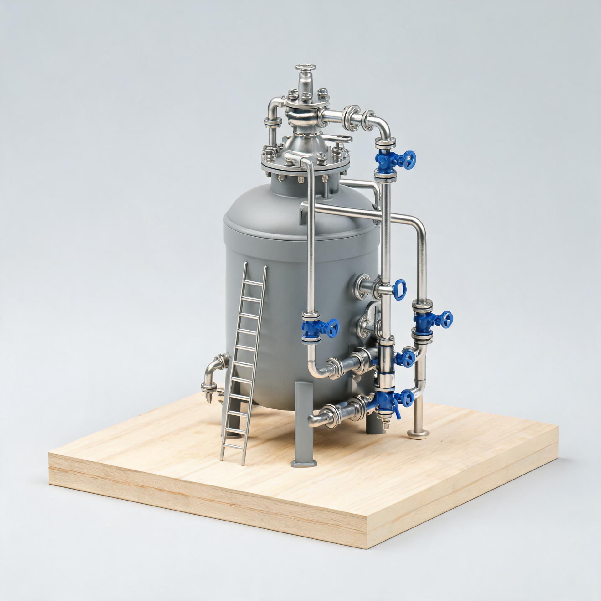
Why a Container Terminal Scale Model Beats a Drawing
Terminals are long, flat and repetitive. Row after row of boxes on asphalt. A drawing shows each block correctly and still explains nothing, because the eye cannot compare density across two sheets of paper.
A model puts the quay line, the yard blocks and the gate on one surface. The bottleneck becomes visible. That is the whole point of a container terminal scale model, and it is why planners ask for one before a capacity study is finished.
Berth, crane and yard in one view
Ship-to-shore cranes are built with the boom raised or lowered. A raised boom reads as capacity. A lowered boom reads as an operating berth. We usually model the crane at 1:200 even when the site runs at 1:500, so the machine keeps its shape instead of turning into a stick.
Future phases in a single tone
Built and unbuilt areas are shown in different treatments. The current terminal keeps full colour. The future phase stays neutral or wireframe. No legend is needed, and the contrast does the arguing.
What the Model Shows at 1:500
- 3000 mm of base covers roughly 1500 m of quay line.
- A 20-foot container measures about 12 mm, enough to show stacking two, three and four high.
- The gate includes lane islands, canopy and OCR portals, because that is where road and rail meet.
- Crane booms are removable, which keeps each crate under 30 kg.
Detail follows the question, not the scale. At 1:500 nobody reads bolts. They read block density, crane spacing and the distance from quay to gate.
How a Container Terminal Scale Model Is Built
- Send the berth plan, yard layout and one elevation. Site photos help with asphalt and water colour.
- Receive a fixed quote in one working day, with scale options and footprint.
- Approve a 3D render. Nothing is cut before that approval.
- Build and crate. Typical lead time is 25 to 35 days, with a numbered setup guide.
Port authorities comparing several terminals often order one masterplan model plus detail inserts. The inserts sit beside the main site and show crane or gate detail at 1:200. It keeps the boardroom view clean without losing the technical argument.
Questions from Port Planners
Can the model show a channel or breakwater?
Yes. Water is cast acrylic with a wave profile, tinted from your site photos. Breakwater and revetment are cut from the same sheet so there is no seam at the waterline. For dredging studies we add depth contours as shallow engraved lines.
How accurate is the yard geometry?
Block positions and aisle widths follow your drawing. We exaggerate a few relationships by five to eight percent so the eye can separate them at two metres. The exaggeration is marked on the 3D review, not hidden.
What reference material do you use?
Terminal layouts follow published guidance from the International Association of Ports and Harbors, and container dimensions follow ISO 668 series standards. If your terminal uses a non-standard box, tell us before production.
Related reading: our urban planning model uses the same block-by-block method, and the industrial model workshop builds the crane and gate detail.
Send your berth layout through the contact page and a fixed quote follows in one working day.