An oil and gas plant scale model has one job: let a room full of people understand a facility they will never walk through. Refineries, LNG terminals and compressor stations are too large, too loud and too dangerous to visit in person. A 1:100 replica puts the whole process chain on a table, in proportion, in five minutes.
SZTXWS builds these models from your P&ID, GA drawings or site photos. Below is what we build, at what scale, and how the quote process works.
What Oil & Gas Plant Models Are Used For
Refinery and petrochemical units
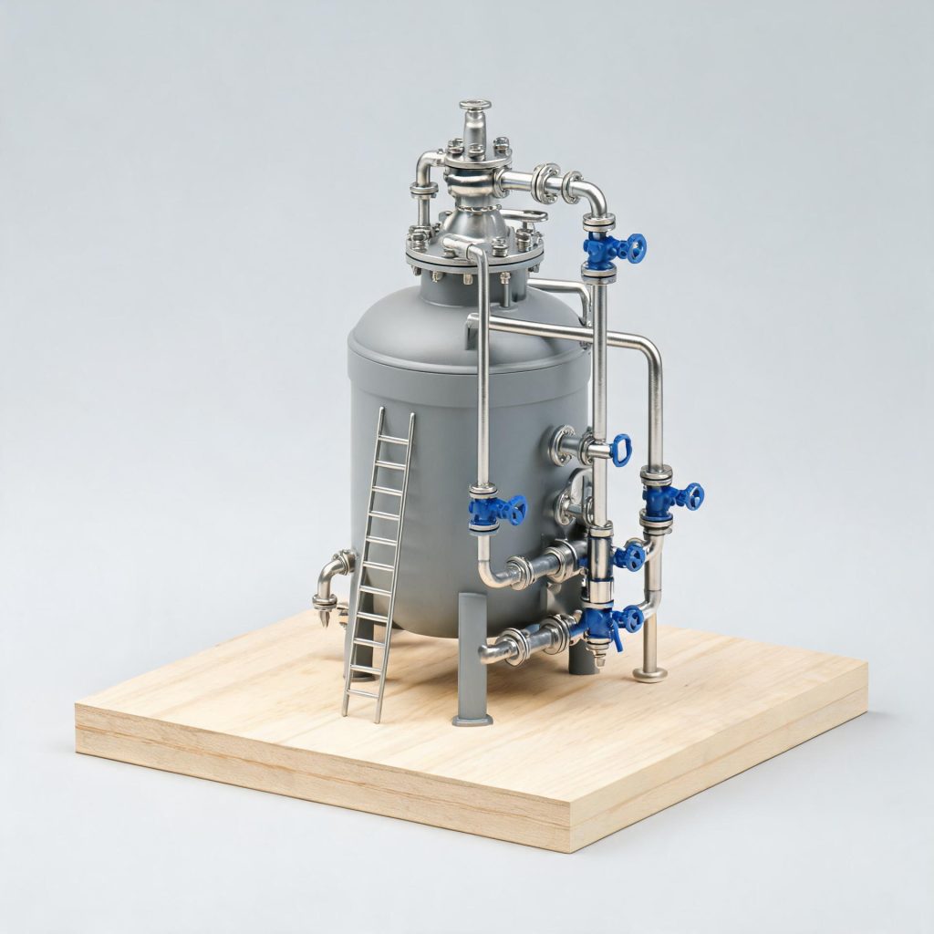
CDUs, vacuum units, hydrocrackers and reformer sections are usually shown as a cutaway block. Pipes are colour-coded by service, and the flare stack is kept at true relative height so viewers grasp the vertical scale of the site.
LNG terminals and regasification plants
Storage tanks dominate these models. We build domed or flat-top tanks with visible roof structure, plus jetty, loading arms and vaporiser banks. Tank diameters typically run 800–1200 mm at 1:200.
Pipeline and compressor stations
For linear assets we build a strip model: a 1:500 spine with compressor skids, pig traps and valve stations placed along the route. Length can reach 3000 mm while keeping the footprint under 600 mm deep.
Scales We Build and What They Cost in Space
- 1:50 — footprint 2000–3000 mm — lobby and investor presentations, close-up detail
- 1:100 — footprint 1200–2000 mm — trade shows and training rooms
- 1:200 — footprint 800–1200 mm — executive offices, several units side by side
- 1:500 — up to 3000 mm long — pipeline and route models
Detail budget matters more than scale. At 1:50 we can show platform gratings, stair runs and pipe racks. At 1:200 we keep the silhouette, colour coding and major equipment; individual bolts and cable trays are dropped on purpose so the model stays readable.
Materials and Detail Level
We use laser-cut acrylic for tanks and structures, ABS or resin for complex skids, and 3D-printed parts where geometry is irregular. Pipe runs are real tube, not printed lines, so they catch light and read as pipe at a distance.
Finish follows the plant palette: safety yellow for structures, grey for vessels, green or blue for pipe services. If your project has a brand colour, we match it against a physical sample before production.
How the Process Works
- Send drawings. P&ID, GA plan, elevation or even a set of site photos with dimensions. A marked-up screenshot is acceptable.
- Quote in one working day. You receive price, scale options, footprint and lead time in one document.
- 3D review before cutting. We share renders for layout and colour sign-off. Nothing is cut until you approve.
- Production and freight. Typical build time is 15–30 days. Models ship in foam-lined crates with a numbered assembly guide, and we support setup by video call.
Need a comparable build for a different process plant? See our coal industry equipment model and chemical equipment model, or the 1:50 production line case.
Questions Buyers Ask
Can you work from a P&ID only?
Yes. A P&ID gives us the process logic and equipment list. We reconstruct geometry from standard unit shapes and confirm proportions with you in the 3D review. If exact dimensions matter for a client presentation, add one GA drawing.
Do you build models with moving parts?
We can add motorised pumps, rotating flare tips and LED flow indication. Motors are 24V and shipped with a plug adapter matched to your destination country.
How is the model protected in transit?
Each unit is crated separately with foam inserts, and fragile items such as loading arms are packed as removable parts. We photograph the packed crate before dispatch. Damage claims are handled by replacement parts, not by rebuilding the model.
Send your drawings through the contact page and you will have a fixed quote in one working day.